name='google-site-verification'/> Marine Engineering 360: June 2016

Thursday, June 30, 2016

Testing and Overhauling of Fuel Injection Valves


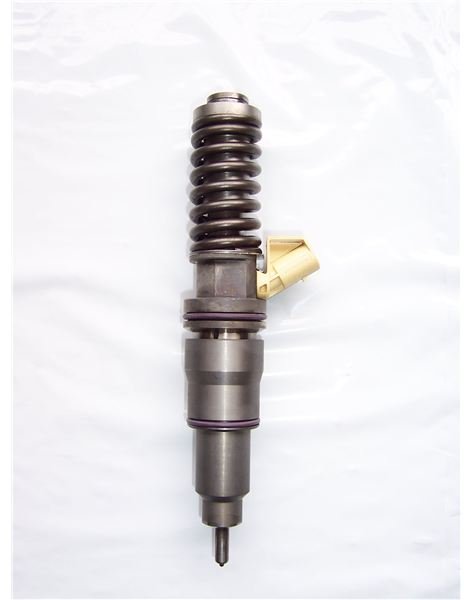
Test and Overhaul of Fuel Injection Valves


The fuel valves taken out from the engine must be checked for function and performance. Even in engines which are stopped on heavy fuel oil in ports the fuel injector taken out must be immediately tested with diesel oil before they get cold as this will flush and clean the components. It must be noted that if the fuel valves taken out are tested after they have cooled, will show bad performance even if they were performing satisfactorily in service.

In the majority of cases the fuel injectors have a good spray profile but they open up at a less pressure. The pressure adjustment can be done without opening up the valve and should be done so. The engine manufacturers also instruct that unless the fuel injector valve has a major problem like holes choked or valve dripping, they should not be opened up. The valve should be cleaned from the outside, pressure checked, pressure adjusted and tagged.

Inspection and Repairs

In the case where the fuel injector valve is not performing as required and has some defect, then it needs to be opened up and overhauled. The assembly and the disassembly have to be done as per the instructions given by the engine manufacturer. However, below is a general guide about what you will most likely have to do.

After the fuel valve has been disassembled then the following checks have to be done:


1. The needle guide should be immersed in clean diesel oil and the needle taken out and checked for free movement. In the case of any resistance which may be due to the presence of carbon or fuel sludge the needle may be put in and pulled out in succession many times while keeping it submerged in diesel oil. It is important to do this in a container full of clean diesel oil so the contaminants can be flushed away.


2. After the needle guide has been cleaned, the needle should be taken almost out and then let it fall in with its own weight. A free and smooth movement with small jerks as the clearance is making way for the oil to come out is an indication that the clearances are all right and the needle guide is in good condition. It must be noted that the needle should fall fully into the seat.

3. On the other hand if the needle falls fully in one go, then the clearances have increased and the fuel will leak past the spindle and less fuel will go in the cylinder. The needle must be inspected for any wear marks if this happens. The needle guide can be used but must be changed soon.

4. If the needle does not go down and gets struck then it must be thoroughly cleaned again. If still there is no improvement then the needle might have become bent. Check the needle for any signs of overheating.

5. The push rod end should be checked for any abnormal wear.

6. The seating between the nozzle body and the valve body if damaged can be repaired by lapping with fine lapping paste. It must be noted that the lapping paste should be thoroughly flushed away with clean diesel oil and thereafter blown dry with compressed air.

7. Check the nozzle spring for breakage, poor seating and other defects. Change if required.

8. Check the leak off pipes, shims, packing etc for the condition. If the fuel valve is water cooled, the cooling pockets should be cleaned with compressed air.

Tests and Adjustments


1. After the parts are cleaned and inspected the fuel valve is assembled as per the manufacturer’s instructions and thereafter tested for function and performance.


2. The assembled fuel valve is installed on the test stand and after purging the pipe line the manual handle is operated in quick succession. The nozzle should start discharging with a sharp crackling noise at the set pressure. The pressure at which the injector is supposed to fire depends upon the manufacturer’s engine design but normally is between 250 to 350 kg/cm2 with an allowance of plus or minus 10 kg/cm2.


3. In case the lifting pressure is not correct, it can be adjusted by the adjusting screw.


4. The spray characteristics should be satisfactory and as per the manufacturers advice.


5. All the holes of the injector should be firing and can be checked by a torch light or a filter paper can be folded as a cone and then the injector tested. The holes on the filter paper will show the number of holes firing. In this procedure you must be careful as the high pressure spray can enter the skin and is toxic for us.


6. The spray angle should be as stated by the manufacturer. The atomization of the fuel should take place and solid spray should not come out.


7. Clean diesel oil should be used for the testing purpose.

8. In the case that the fuel valve is dripping the needle guide should be taken out and repaired.

Caution

The needle and the guide is always a pair and should not be interchanged with another one. Cleanliness is the most important factor in making fuel valves. A clean fuel valve lasts a longer time. The fuel under pressure can enter the skin and the blood stream and is toxic for humans. Take care that you stay away from the spray. The fine mist can catch fire and in inflammable. Do not smoke or use naked lights where the fuel injectors are being tested.
----------------------------------------------------------------------
 Reference:

Causes for Electric Motor Failure

Determining Causes for Electric Motor Failure

It is estimated that 92% of the electric motor failures occur at the start up. Most of these failures occur due to low resistance. Mechanical failures and over-current failures are also very common.

Electric motors are an essential part of our daily life as many systems, applications, and services depend on them. Motors today have a long service life and require a minimum level of maintenance to make sure that they perform efficiently. In large buildings, motors have to be maintained on a regular basis because they need to be in operation all the time; one small problem could cause a great loss to the organization.


Usually in large organizations, a motor maintenance program is carried out in which the causes of motor failures are identified and some necessary steps are taken to avoid them or lower their impact. Motors need to be inspected regularly, and other maintenance activities need to be performed to ensure efficient operation. Whenever a problem occurs, it should be corrected immediately to avoid further loss.

Common Causes of Electric Motor Failures


There are six main causes of electric motor failures:

  1. Over-Current
  2. Low Resistance
  3. Over heating
  4. Dirt
  5. Moisture
  6. Vibration

These causes are briefly explained below:

1. Over-Current (Electrical Overload): In different operating conditions, electrical devices will sometimes start to draw more current than their overall capacity. This unpredictable event will happen very suddenly and will greatly impact the motor. To avoid an over-current, there are some devices that need to be installed that can prevent it from happening. These devices are usually wired in the circuits and will automatically shut down the extra amount of current flowing in the circuit.

2. Low Resistance: Most motor failures occur due to low insulation resistance. This issue is considered to be themost difficult one to tackle. In the initial stages of motor installation, the insulation resistance is observed to be more than one thousand megaohms. After some time, the insulation performance starts to degrade at an alarming level because the resistance starts to decay gradually. After a lot of research, a solution has been found which can prevent low resistance failures. There are automatic devices that test insulation resistance from time to time and safeguard rotating equipment is installed that prevents such failures. It is important that the insulation performance is monitored at regular intervals.

3. Over Heating Excessive heat in motors can cause a number of performance problems. Overheating causes the motor winding insulation to deteriorate quickly. For every ten centigrade rise in temperature, the insulation life is cut in half. It has been concluded that more than 55% of the insulating failures are caused by over heating.

Over heating occurs due to a number of factors. Every electric motor has a design temperature. If a motor is started off at a bad current value, it starts operating in a much warmer condition than the design temperature. It is very important that the motors should be matched with their ideal current values.

Overheating also occurs when an electric motor is forced to operate in a high temperature environment. This causes the rate at which heat can be conducted to reduce at an alarming rate. The area where electric motors are operating must have a proper cooling system and a ventilation system should be there in case the cooling system stops working.


4. Dirt: Dirt is one of the major sources that cause damage to the electric motors. It can damage the motor by blocking the cooling fan which causes its temperature to raise. It can also affect the insulating value of the winding insulation if it settles on the motor windings. Proper steps should be taken to prevent the motors from dirt. Shielding devices are available which are used for this purpose.


5. Moisture:
Moisture also affects the performance of electric motors. It greatly contributes in the corrosion of the motor shafts, bearings and rotors. This can lead to an insulation failure also. The motor inventory should be kept dry all the time.


6. Vibration:
There are a number of possible causes of vibration, such as misalignment of the motor. Corrosion of parts can also cause the motor to vibrate. The alignment of the motor should be checked to eliminate this issue.
----------------------------------------------------------------------
 Reference:

Electrical & Electronic Units


Electrical & electronic units table

Unit NameUnit SymbolQuantity
Ampere (amp)AElectric current (I)
VoltVVoltage (V, E)
Electromotive force (E)
Potential difference (Δφ)
OhmΩResistance (R)
WattWElectric power (P)
Decibel-milliwattdBmElectric power (P)
Decibel-WattdBWElectric power (P)
Volt-Ampere-ReactivevarReactive power (Q)
Volt-AmpereVAApparent power (S)
FaradFCapacitance (C)
HenryHInductance (L)
siemens / mhoSConductance (G)
Admittance (Y)
CoulombCElectric charge (Q)
Ampere-hourAhElectric charge (Q)
JouleJEnergy (E)
Kilowatt-hourkWhEnergy (E)
Electron-volteVEnergy (E)
Ohm-meterΩ∙mResistivity (ρ)
siemens per meterS/mConductivity (σ)
Volts per meterV/mElectric field (E)
Newtons per coulombN/CElectric field (E)
Volt-meterV·mElectric flux (Φe)
TeslaTMagnetic field (B)
GaussGMagnetic field (B)
WeberWbMagnetic flux (Φm)
HertzHzFrequency (f)
SecondssTime (t)
Meter / metremLength (l)
Square-meterm2Area (A)
DecibeldB 
Parts per millionppm 

Units prefix table

Prefix

Prefix
Symbol
Prefix
factor
Example
picop10-121pF = 10-12F
nanon10-91nF = 10-9F
microμ10-61μA = 10-6A
millim10-31mA = 10-3A
kilok10 31kΩ = 1000Ω
megaM10 61MHz = 106Hz
gigaG10 91GHz = 109Hz


Electrical units definitions

Volt (V)

Volt is the electrical unit of voltage.
One volt is the energy of 1 joule that is consumed when electric charge of 1 coulomb flows in the circuit.
1V = 1J / 1C

Ampere (A)

Ampere is the electrical unit of electrical current. It measures the amount of electrical charge that flows in an electrical circuit per 1 second.
1A = 1C / 1s

Ohm (Ω)

Ohm is the electrical unit of resistance.
1Ω = 1V / 1A

Watt (W)

Watt is the electrical unit of electric power. It measures the rate of consumed energy.
1W = 1J / 1s
1W = 1V · 1A

Decibel-milliwatt (dBm)

Decibel-milliwatt or dBm is a unit of electric power, measured with logarithmic scale referenced to 1mW.
10dBm = 10 · log10(10mW / 1mW)

Decibel-Watt (dBW)

Decibel-watt or dBW is a unit of electric power, measured with logarithmic scale referenced to 1W.
10dBW = 10 · log10(10W / 1W)

Farad (F)

Farad is the unit of capacitance. It represents the amount of electric charge in coulombs that is stored per 1 volt.
1F = 1C / 1V

Henry (H)

Henry is the unit of inductance.
1H = 1Wb / 1A

siemens (S)

siemens is the unit of conductance, which is the opposite of resistance.
1S = 1 / 1Ω

Coulomb (C)

Coulomb is the unit of electric charge.
1C = 6.238792×10¹⁸ electron charges

Ampere-hour (Ah)

Ampere-hour is a unit of electric charge.
One ampere-hour is the electric charge that flow in electrical circuit, when a current of 1 ampere is applied for 1 hour.
1Ah = 1A · 1hour
One ampere-hour is equal to 3600 coulombs.
1Ah = 3600C

Tesla (T)

Tesla is the unit of magnetic field.
1T = 1Wb / 1m2

Weber (Wb)

Weber is the unit of magnetic flux.
1Wb = 1V · 1s

Joule (J)

Joule is the unit of energy.
1J = 1 kg · 1(m / s)2

Kilowatt-hour (kWh)

Kilowatt-hour is a unit of energy.
1kWh = 1kW · 1h = 1000W · 1h

Kilovolt-amps (kVA)

Kilovolt-amps is a unit of power.
1kVA = 1kV · 1A = 1000 · 1V · 1A

Hertz (Hz)

Hertz is the unit of frequency. It measures the number of cycles per second.
1 Hz = 1 cycles / s
----------------------------------------------------------------------
 Reference:

Resistors (Details)

What is resistor

Resistor is an electrical component that reduces the electric current.
The resistor's ability to reduce the current is called resistance and is measured in units of ohms (symbol: Ω).
If we make an analogy to water flow through pipes, the resistor is a thin pipe that reduces the water flow.

Ohm's law

The resistor's current I in amps (A) is equal to the resistor's voltage V in volts (V)
divided by the resistance in ohms (Ω):

The resistor's power consumption P in watts (W) is equal to the resistor's current I in amps (A)
times the resistor's voltage V in volts (V):
P = I × V

The resistor's power consumption P in watts (W) is equal to the square value of the resistor's current I in amps (A)
times the resistor's resistance R in ohms (Ω):
P = I 2 × R

The resistor's power consumption P in watts (W) is equal to the square value of the resistor's voltage V in volts (V)
divided by the resistor's resistance R in ohms (Ω):
P = V 2 R

Resistors in parallel

The total equivalent resistance of resistors in parallel RTotal is given by:

So when you add resistors in parallel, the total resistance is decreased.

Resistors in series

The total equivalent resistance of resistors in series Rtotal is the sum of the resistance values:
Rtotal = R1R2R3+...

So when you add resistors in series, the total resistance is increased.

Dimensions and material affects

The resistance R in ohms (Ω) of a resistor is equal to the resistivity ρ in ohm-meters (Ω∙m) times the resistor's length l in meters (m) divided by the resistor's cross sectional area A in square meters (m2):
R=\rho \times \frac{l}{A}

Resistor image

Resistor symbols

resistor symbolResistor (IEEE)Resistor reduces the current flow.
resistor symbolResistor (IEC)
potentiomemer symbolPotentiometer (IEEE)Adjustable resistor - has 3 terminals.
potentiometer symbolPotentiometer (IEC)
variable resistor symbolVariable Resistor / Rheostat (IEEE)Adjustable resistor - has 2 terminals.
variable resistor symbolVariable Resistor / Rheostat (IEC)
Trimmer ResistorPresest resistor
ThermistorThermal resistor - change resistance when temperature changes
Photoresistor / Light dependent resistor (LDR)Changes resistance according to light

Resistor color code

The resistance of the resistor and its tolerance are marked on the resistor with color code bands that denotes the resistance value.
There are 3 types of color codes:
  • 4 bands: digit, digit , multiplier, tolerance.
  • 5 bands: digit, digit, digit , multiplier, tolerance.
  • 6 bands: digit, digit, digit , multiplier, tolerance, temperature coefficient.

Resistance calculation of 4 bands resistor

R = (10×digit+ digit2) × multiplier

Resistance calculation of 5 or 6 bands resistor

R = (100×digit+ 10×digit2+digit3) × multiplier

Resistor types

Variable resistorVariable resistor has an adjustable resistance (2 terminals)
PotentiometerPotentiometer has an adjustable resistance (3 terminals)
Photo-resistorReduces resistance when exposed to light
Power resistorPower resistor is used for high power circuits and has large dimensions.
Surface mount
(SMT/SMD) resistor
SMT/SMD resistors have small dimensions. The resistors are surface mounted on the printed circuit board (PCB), this method is fast and requires small board area.
Resistor networkResistor network is a chip that contains several resistors with similar or different values.
Carbon resistor
Chip resistor
Metal-oxide resistor
Ceramic resistor

Pull-up resistor

In digital circuits, pull-up resistor is a regular resistor that is connected to the high voltage supply (e.g +5V or +12V) and sets the input or output level of a device to '1'.
The pull-up resistor set the level to '1' when the input / output is disconnected. When the input / output is connected, the level is determined by the device and overrides the pull-up resistor.

Pull-down resistor

In digital circuits, pull-down resistor is a regular resistor that is connected to the ground (0V) and sets the input or output level of a device to ' 0 '.
The pull-down resistor set the level to ' 0 ' when the input / output is disconnected. When the input / output is connected, the level is determined by the device and overrides the pull-down resistor.
----------------------------------------------------------------------
 Reference:

ELECTRICAL AND ELECTRONIC SYMBOLS: Part 2


Electrical Symbols & Electronic Symbols

Electrical symbols and electronic circuit symbols are used for drawing schematic diagram.
The symbols represent electrical and electronic components.

Table of Electrical Symbols

SymbolComponent nameMeaning

Wire Symbols

electrical wire symbolElectrical WireConductor of electrical current
connected wires symbolConnected WiresConnected crossing
unconnected wires symbolNot Connected WiresWires are not connected

Switch Symbols and Relay Symbols

SPST switch symbolSPST Toggle SwitchDisconnects current when open
SPDT switch symbolSPDT Toggle SwitchSelects between two connections
push button symbolPushbutton Switch (N.O)Momentary switch - normally open
push button symbolPushbutton Switch (N.C)Momentary switch - normally closed
dip switch symbolDIP SwitchDIP switch is used for onboard configuration
spst relay symbolSPST RelayRelay open / close connection by an electromagnet
spdt relay symbolSPDT Relay
jumper symbolJumperClose connection by jumper insertion on pins.
solder bridge symbolSolder BridgeSolder to close connection

Ground Symbols

earth  ground symbolEarth GroundUsed for zero potential reference and electrical shock protection.
chassis symbolChassis GroundConnected to the chassis of the circuit
common digital ground symbolDigital / Common Ground

Resistor Symbols

resistor symbolResistor (IEEE)Resistor reduces the current flow.
resistor symbolResistor (IEC)
potentiomemer symbolPotentiometer (IEEE)Adjustable resistor - has 3 terminals.
potentiometer symbolPotentiometer (IEC)
variable resistor symbolVariable Resistor / Rheostat (IEEE)Adjustable resistor - has 2 terminals.
variable resistor symbolVariable Resistor / Rheostat (IEC)
Trimmer ResistorPreset resistor
ThermistorThermal resistor - change resistance when temperature changes
Photoresistor / Light dependent resistor (LDR)Photo-resistor - change resistance with light intensity change

Capacitor Symbols

CapacitorCapacitor is used to store electric charge. It acts as short circuit with AC and open circuit with DC.
capacitor symbolCapacitor
polarized capacitor symbolPolarized CapacitorElectrolytic capacitor
variable capacitor symbolVariable CapacitorAdjustable capacitance

Inductor / Coil Symbols

inductor symbolInductorCoil / solenoid that generates magnetic field
iron core inductor symbolIron Core InductorIncludes iron
variable core inductor symbolVariable Inductor

Power Supply Symbols

voltage source symbolVoltage SourceGenerates constant voltage
current source symbolCurrent SourceGenerates constant current.
ac power source symbolAC Voltage SourceAC voltage source
generator symbolGeneratorElectrical voltage is generated by mechanical rotation of the generator
battery cell symbolBattery CellGenerates constant voltage
battery symbolBatteryGenerates constant voltage
controlled voltage source symbolControlled Voltage SourceGenerates voltage as a function of voltage or current of other circuit element.
controlled current source symbolControlled Current SourceGenerates current as a function of voltage or current of other circuit element.

Meter Symbols

voltmeter symbolVoltmeterMeasures voltage. Has very high resistance. Connected in parallel.
ammeter symbolAmmeterMeasures electric current. Has near zero resistance. Connected serially.
ohmmeter symbolOhmmeterMeasures resistance
wattmeter symbolWattmeterMeasures electric power

Lamp / Light Bulb Symbols

lamp symbolLamp / light bulbGenerates light when current flows through
lamp symbolLamp / light bulb

Diode / LED Symbols

diode symbolDiodeDiode allows current flow in one direction only - left (anode) to right (cathode).
zener diodeZener DiodeAllows current flow in one direction, but also can flow in the reverse direction when above breakdown voltage
schottky diode symbolSchottky DiodeSchottky diode is a diode with low voltage drop
varicap diode symbolVaractor / Varicap DiodeVariable capacitance diode
tunnel diode symbolTunnel Diode
led symbolLight Emitting Diode (LED)LED emits light when current flows through
photodiode symbolPhotodiodePhotodiode allows current flow when exposed to light

Transistor Symbols

npn transistor symbolNPN Bipolar TransistorAllows current flow when high potential at base (middle)
pnp transistor symbolPNP Bipolar TransistorAllows current flow when low potential at base (middle)
darlington transistor symbolDarlington TransistorMade from 2 bipolar transistors. Has total gain of the product of each gain.
JFET-N transistor symbolJFET-N TransistorN-channel field effect transistor
JFET-P transistor symbolJFET-P TransistorP-channel field effect transistor
nmos transistor symbolNMOS TransistorN-channel MOSFET transistor
pmos transistor symbolPMOS TransistorP-channel MOSFET transistor

Misc. Symbols

motor symbolMotorElectric motor
transformer symbolTransformerChange AC voltage from high to low or low to high.
Electric bellRings when activated
BuzzerProduce buzzing sound
fuse symbolFuseThe fuse disconnects when current above threshold. Used to protect circuit from high currents.
fuse symbolFuse
bus symbolBusContains several wires. Usually for data / address.
bus symbolBus
bus symbolBus
optocoupler symbolOptocoupler / Opto-isolatorOptocoupler isolates connection to other board
speaker symbolLoudspeakerConverts electrical signal to sound waves
microphone symbolMicrophoneConverts sound waves to electrical signal
operational amplifier symbolOperational AmplifierAmplify input signal
schmitt trigger symbolSchmitt TriggerOperates with hysteresis to reduce noise.
Analog-to-digital converter (ADC)Converts analog signal to digital numbers
Digital-to-Analog converter (DAC)Converts digital numbers to analog signal
crystal oscillator symbolCrystal OscillatorUsed to generate precise frequency clock signal

Antenna Symbols

antenna symbolAntenna / aerialTransmits & receives radio waves
antenna symbolAntenna / aerial
dipole antenna symbolDipole AntennaTwo wires simple antenna

Logic Gates Symbols

NOT gate symbolNOT Gate (Inverter)Outputs 1 when input is 0
AND gate symbolAND GateOutputs 1 when both inputs are 1.
NAND gate symbolNAND GateOutputs 0 when both inputs are 1. (NOT + AND)
OR gate symbolOR GateOutputs 1 when any input is 1.
NOR gate symbolNOR GateOutputs 0 when any input is 1. (NOT + OR)
XOR gate symbolXOR GateOutputs 1 when inputs are different. (Exclusive OR)
D flip flop symbolD Flip-FlopStores one bit of data
mux symbolMultiplexer / Mux 2 to 1Connects the output to  selected input line.
mux symbolMultiplexer / Mux 4 to 1
demux symbolDemultiplexer / Demux 1 to 4Connects selected output to the input line.

Electronic Components

Electronic components are parts of electrical & electronic circuits. Each component has typical functionality according to its operational characteristics.

Electrical and electronic components table

Component ImageComponent SymbolComponent Name
Wire
Toggle switch
Pushbutton switch
Relay
Jumper
Dip switch
Resistor
Variable resistor / Rheostat
Potentiometer
Capacitor
Variable capacitor
Electrolytic capacitor
Inductor
Battery
Voltmeter
Lamp / Light bulb
Diode
BJT Transistor
MOS transistor
Optocoupler / optoisolator
Electric motor

Transformer
Operational amplifier / 741
Crystal oscillator
Fuse
Buzzer
Loudspeaker
Microphone
Antenna / aerial

Passive components

Passive components do not need additional power source to operate and can not have gain.
Passive components include: wires, switches, resistors, capacitors, inductors, lamps, ...

Active components

Active components need additional power source to operate and can have gain.
Active components include: transistors, relays, power sources, amplifiers, ...
----------------------------------------------------------------------------------------